ENERGY LEADERS EMERGE ON MAY 3RD

Energized Students Demonstrate Skills at the EnergyWhiz Olympics on the Space Coast

WHAT:

The 12th annual EnergyWhiz Olympics will bring together students from across Florida, converging in Cocoa, to showcase their renewable energy projects. Student teams will race solar cars, demonstrate creative solar and hydrogen projects, present solar oven designs and cooking skills, and reveal energy-efficient pet homes, all highlighting their energy knowledge and skills in Science, Technology, Engineering, Art and Math (STEAM).

NEW:  An Electric Vehicle Ride & Drive—which will include a Nissan Leaf—will be available for adults to experience.

The public is invited to attend free of charge.

Read more

DOT Selects UCF to Develop ‘Smart Grid’ for Plug-in Electric Vehicles

By Sherri Shields

COCOA, October 24, 2013 – As interest in electric vehicles continues to keep the automotive industry charged, the nation is strategizing how to best integrate plug-in vehicles with its electrical grid and highways. Now, with funding from the U.S. Department of Transportation for the creation of the first transportation center with a focus on electric vehicles, the University of Central Florida will help chart that course in Florida.

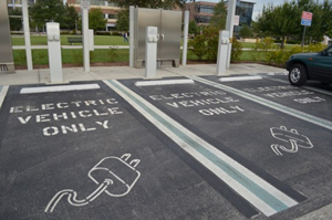
Photograph of electric vehicle only parking
Dedicated parking and charging stations for electric vehicles might soon become commonplace.

The Electric Vehicle Transportation Center operated by UCF’s Florida Solar Energy Center is a newly funded, four-year, $9 million research effort to help create the nation’s electric-vehicle transportation network. Research conducted by the center will help transportation planners prepare our nation’s highways for the influx of plug-in electric vehicles (PEV), while developing “smart grid” applications that will strengthen the ability of our electric system to accommodate the power demands of electric vehicles. PEVs need a reliable, predictable network of charging stations to allow them to travel long distances without the fear of “running out of fuel.” Workplace charging, community charging, and highway fast-charging systems are in development. A new PEV transportation network designed in conjunction with the modernization of our electric grid system will result in a sustainable highway and energy network.

Read more

In the Field with Neil: RESNET Chapter 8 Blower Door Numbers

In July 2013 – Florida changed; some say for the better – others not so much so. Never the less, change has occurred. For raters working in Florida, it means that we now have the option in how we perform blower door testing. In the past, it was a requirement that for a registered rating – a multipoint test was needed. Now we can do a single point. (For me personally, I like the multipoint test. All the hard work is done; I only need to gather a few building pressures and corresponding flows. I get more info about the building enclosure. But this is for another blurb.)

So what does RESNET chapter 8 say…

802.1 ON-SITE INSPECTION PROTOCOL

There are three acceptable airtightness test procedures:

802.1.1 Single-point test: Measuring air leakage one time at a single pressure difference as described in section 802.5

802.1.2 Multi-point test: Measuring air leakage at multiple induced pressures differences as described in section 802.6

802.1.3 Repeated single-point test: The test is similar to the single point test, but the test is done multiple times for improved accuracy and estimating uncertainty as described in section 802.7


What are the highlights of each test process?

(Note that the house setup is identical no matter which test procedure you use – the difference is in the pressures and flows taken from the blower door.)

Let’s look at 802.5 Single-point test.

  1. Determine the baseline range – Fan sealed, record 5 different pressures (10 second average minimum) of house wrt outside. Find the difference between the highest and lowest values – This sets the Level of Accuracy.
  2. Determine the Pre-test baseline pressure – Average these 5 readings just taken may be used (or use baseline feature of meter – 10 second min).
  3. Determine the unadjusted building pressure and flow at 50 pascals – the building pressure to the nearest 0.1 pascal and the flow to the nearest cfm. Also record inside/outside temperatures, fan/meter models/serial numbers, fan configuration and type of test (pressurize/depressurize).
  4. Perform calculations to determine corrected CFM50. See the RESNET Standard section 802.5.9 for that process. Or my suggestion is to download the FREE EnergyConservatory Tectite 4.0 (wifi) software. You can select this test type and just input your numbers and out pops the result and you can save it for later viewing – like when the QA person comes around and asks to see your files…just saying.
  5. If you are using EnergyGauge USA (of course), enter the building pressure and corrected fan flow as shown. Click on Calculate/Post and it will do the calculations needed.

august

Now let’s look at 802.6 Multi-point test.

  1. Determine the Pre-test baseline pressure – Measure the house wrt outside using the 10 second average minimum (or use baseline feature of meter – 10 second min). Fan sealed during this step.
  2. Determine the unadjusted building pressures and flows– Take and record a minimum of 7 additional unadjusted building pressure and nominal fan flow measurements at target induced pressures which are approximately equally-spaced between 60 Pa (or the highest achievable induced building pressure) and 15 Pa. The building pressures to the nearest 0.1 pascal and the flows to the nearest cfm. Also record inside/outside temperatures, fan/meter models/serial numbers, fan configuration and type of test (pressurize/depressurize).
  3. Determine the Post-test baseline pressure – Measure the house wrt outside using the 10 second average minimum (or use baseline feature of meter – 10 second min). Fan sealed during this step
  4. Complete steps #4 & #5 above.
  • Note: the current version of EnergyGauge USA doesn’t do the required adjustments to the as measured building pressures and flows – therefore download the FREE EnergyConservatory Tectite 4.0 (wifi) software; it will perform all the calculations needed.

Lastly look at 802.7 Repeated single-point test.

  1. Determine the Pre-test baseline pressure – Average these 5 readings just taken may be used (or use baseline feature of meter – 10 second min).
  2. Determine the unadjusted building pressure and flow at 50 pascals – the building pressure to the nearest 0.1 pascal and the flow to the nearest cfm. Also record inside/outside temperatures, fan/meter models/serial numbers, fan configuration and type of test (pressurize/depressurize).
  3. Repeat steps #1 & #2 a minimum of 5 times.
  4. Calculate the Average Nominal CFM50 by summing the individual nominal CFM50 readings and dividing by the number of readings.
  5. Perform calculations to determine corrected CFM50. See the RESNET Standard section 802.7.9 for that process or use the FREE EnergyConservatory Tectite 4.0 (wifi) software. If you are using EnergyGauge USA, enter the building pressure and corrected fan flow. Click on Calculate/Post and it will do the calculations needed.

Tei Explains It: August Rater Updates

Continue to stay up-to-date on the latest rater news and announcements.

NATE/RESNET HVAC Performance Verifier Exam

NATE is beta testing the NATE/RESNET HVAC Performance Verifier exam in July and August, 2013. Beta testing is done to make sure we have the right questions, we have the right approach and to receive industry input into the development. The beta exam is now available for HERS raters to take.

Several weeks ago, HERS raters were sent an invitation to take the NATE/RESNET exam at FSEC. The response on the registration page was great however the majority of those that signed up did not show up for the exam. In the future, if you will not be attending a class, test, etc that you have signed up in the FSEC store, please drop us an e-mail or call to cancel. This has been pretty disappointing since there was no cost for this exam.

The next exam is available on August 30 starting at 9:00 AM at FSEC. Registration is available at https://secure.fsec.ucf.edu/fsecstore/do/product/BldgExams/NATEexam

Rater Agreements

The EnergyGauge Office has been working on a HERS Rater packet. This packet should be going out in the early fall. This packet will contain specifics in what we expect from raters and what you can expect from the EnergyGauge Office. Please look for it in your mailboxes. You will have 30 days to execute the agreement after receipt.

Quality Assurance

Quality Assurance for the 2013 year is in full swing. I will be contacting you via e-mail and/or phone to schedule dates and times to get this done. I have complete confidence that you will cooperate fully with this process. Unfortunately, even if you do one home, I will have to get into that home. RESNET is enforcing this and if you do not respond the only choice that I have will be to suspend you from registering ratings. We will be adopting a formal policy regarding this situation and others concerning QA and will be included in your rater packet which should be going out to all HERS raters in the early fall.

Combustion Classes

You will have until January 1, 2015 to complete the combustion portion of your individual certifications. I know we have cancelled classes in the past because the exam was not ready. The exam is now ready and the fall class scheduled for November 19-21 will be held. Register at https://secure.fsec.ucf.edu/fsecstore/do/product/BLDG/Combust
In The Field With Neil: RESNET-Approved Airflow Measurement Techniques

Chapter 8, section 804 of the RESNET Standard provides us with an onsite procedure for measuring the airflow of ventilation systems. These procedures treat the air flows into a grille and out of a register measured separately. There are 3 RESNET-approved test processes used to determine airflow: 1) powered flow hood, 2) air flow resistance and 3) timed bag inflation. Each method, as most things in life, has positives and negatives.


Powered Flow Hood

powerflow

The powered flow hood method is the most accurate, but also the most expensive. The powered flow hood differs from a conventional flow hood in that there is a fan which assists air movement through the flow hood to prevent a pressure differential at the register or grill created by the flow hood. The most common is the Energy Conservatory FlowBlaster® which works with your existing Duct Blaster Fan and DG-700 Pressure and Flow Gauge. The fan is powered by a combination fan speed controller and rechargeable Lithium-Ion battery. This method may be used on either exhaust or supply systems.


Air Flow Resistance

airflow

The air flow resistance method is probably the most common and can only be used on exhaust systems (air entering grill).  This method determines the air flow by measuring a pressure difference across a known hole size.  The air flow (in cfm) is equal to the hole size (in square inches) times 1.07 times the square root of the pressure difference (in pascals).  (Yes we are mixing units, but the 1.07 factor takes care of the conversions.)  This device will give the best results when the pressure difference is less than 8 pascals – largely because the exhaust fan speed will be reduced with greater pressures.  There is a commercially available “box” or flow meter again from the Energy Conservatory or you can easily create your own.  (If interested in creating your own – drop me a line and I will send you the directions.)


bag

Timed Bag Inflation

The timed bag inflation method is the least expensive of all.  It can only be used on supply systems.  As the name implies, a bag (typical a garbage bag) of known volume is inflated by the supply air.  The time required to fully inflate the bag is measured with a stopwatch.  This method takes a bit of practice to get repeatable results, but is rather simple to do.  As the standard indicates, bag volume and thickness play into the accuracy of the results – so a trial and error approach is needed.  Aim for a fill time of 2 to 20 seconds – the longer fill time will be easier to do, but may require a fairly large bag depending on the amount of airflow.  The airflow is easily calculated by multiplying the bag volume (in gallons) by 8 and dividing by the time (in seconds) required to fill it.  The Canada Mortgage and Housing Corporation has a nice write up on the method along with a table to convert to airflow.


These three procedures are the only RESNET-approved methods for measuring airflow in either whole house or spot ventilation systems.  (Well, there is one exception – if an ERV/HRV manufacturer has ports installed on their device for the purpose of measuring airflow; that may be used when following their directions.)

So go measure and have fun out there…